Looking at the wet bulb temperatures for Gambia we can see that there is little cooling in the rainy season (June to Oct) when the humidity is high. So I was thinking if there was some way of reducing humidity so we could deliver effective evaporative cooling all year round.
It turns out there are certain (hygroscopic) materials which have an affinity to draw moisture from air (adsorption). So if we were to pass this a hygroscopic material (desiccant) it would come out drier so would give a lower wet bulb temperature (more effective evaporative cooling).This process is called adsorptive cooling and has already been used for storage of vaccines and food in developing countries (reference).
But maybe we could improvement on this by taking the cold air coming out of the evaporative cooler, drying it again, and the cooling it even further by sending it though another stage of evaporative cooling.
I have shown this proposed process on the psychometric chart below, using the example of typical ambient air during the day in the rainy season in Gambia (30oC , 80% relative humidity).

Figure 1: Comparison of direct evaporative cooling to proposed two stage adsorption cooling process
Regeneration methods
Now in order for this process to be continuous it would require some method of removing moisture (desorption) from the desiccant.If the desiccant is liquid (eg. Saturated Calcium Chloride solution), the diluted solution (after water is adsorbed from wet air) is usually dried by pumping it through a heat exchanger causing the water to boil off, thus re-concentrating it and so allowing it to adsorb more moisture from incoming air, as shown in the diagram below.
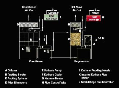
Figure 2: Conventional method of dehumidifying air by adsorption and regeneration of liquid desiccant
However, pumping the solution through a heat exchanger would require a significant electrical power input. Maybe we could use the following alternative process:
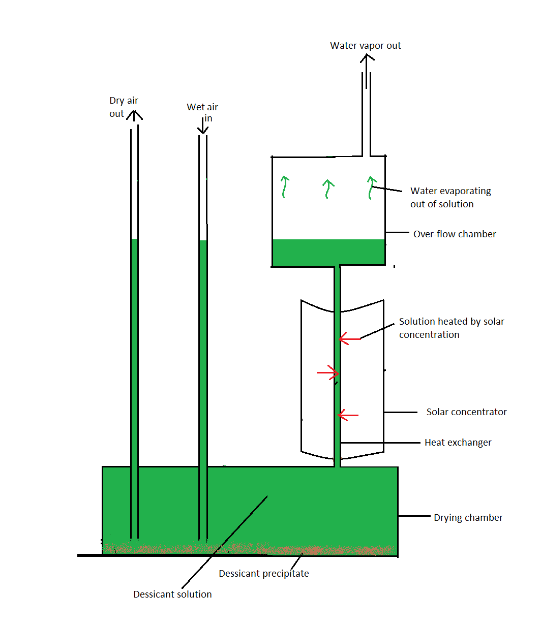
Figure 3: Proposed method of dehumidifying air and regenerating liquid desiccant without requiring any electrical inout for pumping.
A drying chamber is filled with the saturated solution; with excess solid precipitate of the desiccant of added.
Air is passed through the solution causing it to dry out, giving up its moisture to the desiccant. This causes the solution to dilute and therefore its volume increases.
As the volume of the solution increases, it overflows the drying chamber and is is forced by constriction into the heat exchanger. The heat exchanger is simply a pipe with solar radiation concentrated on it by a parabolic solar trough.
This solar heating causes the extra water to evaporate off maintaining the saturation of the solution without the use of any electrical power requirement for pumping.
If the desiccant is a solid (eg. Charcoal, silica gel, activated alumina, lithium chloride salt or synthetic polymers) a usually this system is regenerated (re-dried) using a rotary desiccant wheel.
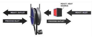
Some air is superheated, by solar concentration/ collection and blown and also passed though the wheel for desorption.
The rotation of the wheel allows for the continuous and simultaneous adsorption and desorption.
However the rotation of the wheel would also required a significant electrical power input. Maybe we could achieve the same end without even moving the porous desiccant material, since if part of it is maintained dry by blowing hot air though and the other is being wetted by adsorption from incoming wet air, this would set up a water concentration gradient from the wet to the dry part, across which the water could flow by osmosis, since the material itself would be a semi-permeable membrane due to its porosity.
Of course this process would not be as fast as using rotating wheel, but maybe if we chose an optimum porous material and desiccant and possible some other substance to catalyse the diffusion process this process could become feasible.
Overall process
I have set out a flow diagram to explain the overall process (in this case assuming the use of a solid porous desiccant: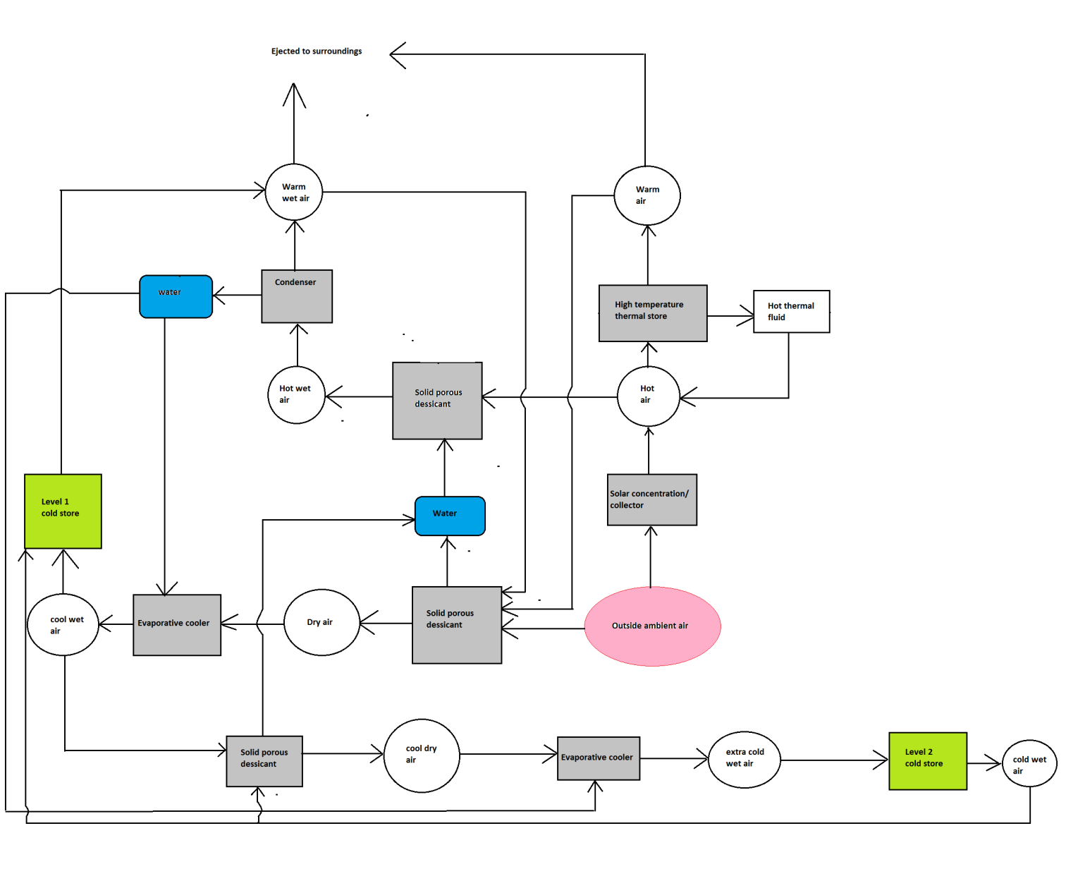
Figure 4: Flow diagram to explain the proposed process two stage adsorption / evaporative cooling
As suggested in this diagram, we could recycle part of the desorbed from the desiccant by the hot air in the regeneration process by passing though a condenser cooled by ambient air. This recycled water could be used to feed the evaporative cooling process. Calculations are required to verify the feasibility of obtaining all the water needed for this process by this method.
Supplementary water and heat backup
If more water is required this could be provided by the intermittent addition of water from a nearby well as this will definitely be available in any location where there is vegetable farming activity.If a groundwater supply is provided this could also function as am additional cold sink to cool the condenser and also the incoming ambient air as this water is usually significantly colder than the ambient air during the day as there is a thermal lag due to the time required for the sun to heat the large underground reservoirs.
Similarly if our calculations were to suggest there maybe times when there is insufficient supply from the solar concentrator, this could be supplemented by burning firewood, cow dung, waste agricultural material, charcoal or cooking gas.
This could require a display and alarm on the control system which would alert the users when water / heat levels are critically low so they could the required actions accordingly.
Two level cooling
Also, as shown in the flow chart, it should be possible to provide to levels of cold storage using this method. The first level would be moderately cool, supplied by air from the first cycle of evaporative cooling. The second level would be further chilled using air from the second stage of cooling.This would allow the system to be used for simultaneous storage of a greater variety of fruit and vegetables (and maybe even dairy products) all within their optimum conditions.
Termite inspired natural ventilation
The entire process would required significant flow rates of air, through the desiccant dehumidifiers, the evaporative coolers, over and through the condenser, and for the circulation of air within the cold stores which would require a significant electrical power input if driven by fans.So maybe we could cleverly make use of natural buoyancy forces (hot air rises, cold air sinks) to drive the flow of air instead, just as termites do to control the temperature of their mounds.
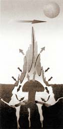
Figure 5: Termites’ use natural convection to ventilate their mounds
Within these mounds the termites control the exact temperature of a certain section at the optimum level for farming fungus for their food, and also another separate section is maintained at the optimum temperature for the Queen termite! This control is maintained perfectly throughout the year despite the dramatically variable day/night, daily and seasonal temperature and humidity environmental conditions they are situated in.
The process is controlled by an elaborate network of channels which draw cold air in from the bottom and ventilate hot air out though the top. The termites open and close thousands of tiny ducts all over the mound (using mud and their saliva) to control the conditions in the mound to their exact requirements.
Now in our case we could use a micro-processor system taking inputs from humidity and temperature sensors at the critical points in the system and accordingly opening/closing valves (as output) to control the flow of air though a network of pipes / ducts to ultimately control the temperatures in the cold stores.
Here is a link found by Tancio which describes research at Loughborough University along the lines I have outlined above :
ReplyDeletehttp://www.iom3.org/news/natural-ventilation-buildings-based-termite-mounds
sir we thought of building a small vapour refrigeration absorption system.we dont have any idea how to design practically.,how to move on so and so.please send us some text materials or video links if possible.vindme0007@gmail.com
ReplyDelete