Now I need to build some control system for the prototypes of these systems.
Flow rate
In order to design the electrical circuit we will need to know the required power supply to the pump, which will be determined by the flowrate required from the pump which will be determined by:
1) temperature of the cold store should be maintained :lets say 10oC as a target to start with)
2) the heat exchangers: as per air-side HE, acquired from back of fridge in skip with configuration as shown below (still need to measure pipe bore and thickness - material = steel):
This heat exchanger has 100 fins (50 front - 50 back) over its surface. However may be too big to fit it all in our prototype cold store (a small fridge) and so we can cut it down if required.
(For the cold thermal fluid store side HE, im not sure what we are going to use - because this needs to be under pressure and also contain a significant mass of fluid as it is the evaporator of the absorption system. ... do you even need an effective heat exchanger design as there would the same amount of heat be extracted from the surroundings regardless of design .s For normal heat exchange processes, for a given temperature difference, increasing the heat exchange surface area and conductivity will increase rate of heat transfer.... but in our case there is no temperature differential driving the process it is the vaporisation of the refrigerant which would draw the same amount of heat (depending on mass vaporised) regardless of these heat exchanger parameters.... hrreer maybe the heat extracted from the surrounding of the total heat removed by evaporation (remaining part drawn from air/gas side inside evaporator?) would be proportional to the heat exchanger effectiveness... therefor it would be critical....?)
3) Coolant :lets use water - or salt water as this has a lower freezing temp
4) volume of air to be cooled: 40 litres (waeco fridge)
Electrical
Have acquired a car batter (12v, 380 A) and a car windscreen pump (12v) from a scrap yard and some crocodile clips, 2 variable resistors (0-1K and 0- 4.7K ohms) and a PTC thermistor (1.19K ohm @ 100oC; 15K ohm @ 25oC; 45.13 ohm@ 0oC) from Maplins.
Was thinking the circuit would look something like this:
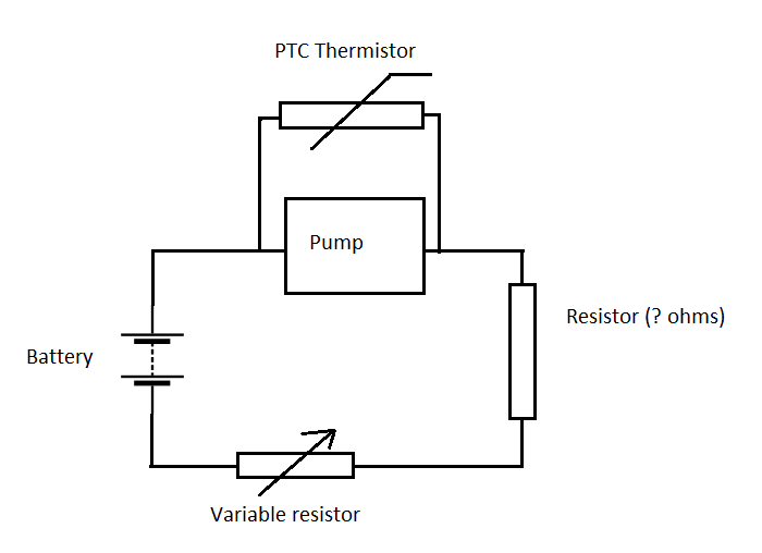
So when the temperature in the cold store is too high the resistance of the thermistor would be high, so more current would be drawn through the pump arm of the circuit, driving the pump faster and thus cooling the cold store and visa-versa.
The variable resistor would be used to set the constant temperature (lower resistance = more power to pump = cooler)
The second constant resistance component would be used ensure the overall resistance of the circuit is adequate.
Now since I did not have enough information about the components exact specifications I tried to find a working solution by playing with different configurations. Whatever I tried, the pump would wither run at full power or zero. I eventually gave up with this method when I fried my other thermistor (NTC one) and the variable resistors started glowing red!
Will need to work on this...
Flow rate
In order to design the electrical circuit we will need to know the required power supply to the pump, which will be determined by the flowrate required from the pump which will be determined by:
1) temperature of the cold store should be maintained :lets say 10oC as a target to start with)
2) the heat exchangers: as per air-side HE, acquired from back of fridge in skip with configuration as shown below (still need to measure pipe bore and thickness - material = steel):
This heat exchanger has 100 fins (50 front - 50 back) over its surface. However may be too big to fit it all in our prototype cold store (a small fridge) and so we can cut it down if required.
(For the cold thermal fluid store side HE, im not sure what we are going to use - because this needs to be under pressure and also contain a significant mass of fluid as it is the evaporator of the absorption system. ... do you even need an effective heat exchanger design as there would the same amount of heat be extracted from the surroundings regardless of design .s For normal heat exchange processes, for a given temperature difference, increasing the heat exchange surface area and conductivity will increase rate of heat transfer.... but in our case there is no temperature differential driving the process it is the vaporisation of the refrigerant which would draw the same amount of heat (depending on mass vaporised) regardless of these heat exchanger parameters.... hrreer maybe the heat extracted from the surrounding of the total heat removed by evaporation (remaining part drawn from air/gas side inside evaporator?) would be proportional to the heat exchanger effectiveness... therefor it would be critical....?)
3) Coolant :lets use water - or salt water as this has a lower freezing temp
4) volume of air to be cooled: 40 litres (waeco fridge)
Electrical
Have acquired a car batter (12v, 380 A) and a car windscreen pump (12v) from a scrap yard and some crocodile clips, 2 variable resistors (0-1K and 0- 4.7K ohms) and a PTC thermistor (1.19K ohm @ 100oC; 15K ohm @ 25oC; 45.13 ohm@ 0oC) from Maplins.
Was thinking the circuit would look something like this:
So when the temperature in the cold store is too high the resistance of the thermistor would be high, so more current would be drawn through the pump arm of the circuit, driving the pump faster and thus cooling the cold store and visa-versa.
The variable resistor would be used to set the constant temperature (lower resistance = more power to pump = cooler)
The second constant resistance component would be used ensure the overall resistance of the circuit is adequate.
Now since I did not have enough information about the components exact specifications I tried to find a working solution by playing with different configurations. Whatever I tried, the pump would wither run at full power or zero. I eventually gave up with this method when I fried my other thermistor (NTC one) and the variable resistors started glowing red!
Will need to work on this...
No comments:
Post a Comment